
For a printable version including pictures, please download them from the online archive: https://northsurveying.com/index.php/soporte/manual-download
North SmaRTK
Quick Operation Guide
SmartOS Version 1.0.9
a.- INTRODUCTION
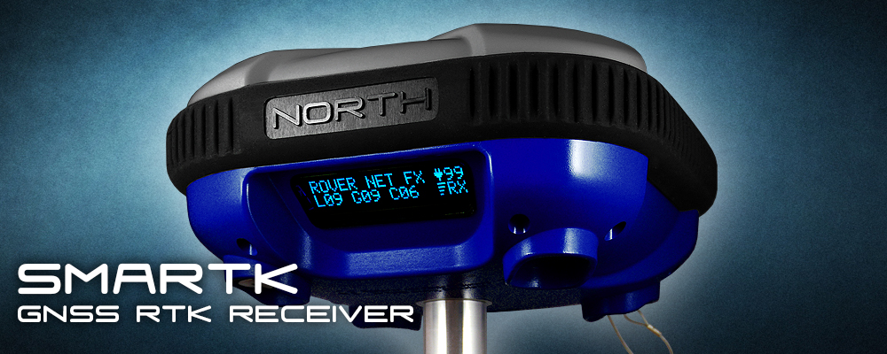
The North SmaRTK is a GNSS RTK receiver designed to be the simplest to use, and to be compatible with most platforms and communication protocols.
The SmaRTK receiver has a mainframe that operates with the SmartOS Operative System on board, that is designed for a flexible and simple use, with the main feature of being able to be upgraded to add new features over time on the same hardware.
This guide show the quick setup of the SmaRTK receiver system along with SmartOS 1.0.9 Operating System in order to get immediate results
This guide assumes that:
1.- You have a Controller device with Bluetooth and a Controller software compatible with NMEA sentences.
2.- You have basic knowledge of Geodesy, GNSS systems and RTK field operation.
3.- The only protocols that you require to operate are NMEA 0183, RTCM 3.0 and RINEX 3.0.
4.- “SmaRTK” stands for a fully featured GNSS SmaRTK receiver with internal UHF radiomodem, external radio-modem amplifier and the full set of accompanying software.
Important Note: For other options and detailed information regarding the SmaRTK receivers or the SmartOS software, please review their particular manuals.
b.- BASIC HARDWARE OPERATION
The SmaRTK unit have the following interfaces;
- Bluetooth Radio-Modem. This is the main operational interphase of the SmaRTK. It is used to receive the data as well as to send the configuration parameters of the receiver.
Important Note: The Bluetooth is permanently ON on all the Rover operational modes. On the Base operational modes as well as in the Static Postprocessing mode, the Bluetooth radio is kept is off on most menus, except on the “Settings” Sub-Menu, to allow to change the SmaRTK settings at any time. The Bluetooth is off in order to save battery when is not needed.
- OLED Display: All indications and operational data is shown on this screen.
- Push Button: All user-input operations are made with this single button and the following inputs:
Long-Press (3 seconds) used to:
- Turn on the SmaRTK
- Enter to the Configuration Menu
- Enter to a Sub-menu or Function
- Set and Option and exit a Sub-Menu
- Turn off the SmaRTK
Short-Press (half second) used to:
- Change Options in a Menu or Sub-Menu
- Start and Stop the logging of Static Post-processing data.
- Micro-SIM Card Slot: Receives the Micro-SIM card of any mobile network operation. The internal modem is unlocked, quad-band and requires that the Micro-SIM card has PIN code exactly “1111”. The Mobile Network is used on the ROVER NETWORK and AUTO-CASTER receiver modes.
- TNC Connector: Used to connect the Receiving or Transmitting antennas to the internal UHF radio-modem. It is also used to connect the internal UHF radio-modem to the external U-Caster UHF radio-modem booster.
- 7-Pin LEMO Connector: Used to connect the North-exclusive Y-Cable. The Y-Cable can be used to charge the internal rechargeable batteries, to operate continuously the SmaRTK with external power, or to connect by USB to a PC to download recorded Static Data or to read real-time NMEA navigation data.
Warning: The LEMO port can be used to connect external 12VDC power to the SmaRTK for continuous operation. The power source can be a car battery or a wall plug. However, crossing the polarity of the power source would result in immediate and permanent damage to the SmaRTK. This kind of damage is not covered by North's warranty. If you are not sure of what to do, please contact our support center.
Important Note: The LEMO Connector also can be used with a standard Serial cable for common RS232 interfaces.
c.- BASIC SOFTWARE OPERATION
- To turn on the SmaRTK Long-Press the button. The display will start, show the serial number and SmartOS version, and then enter to the Main Screen.
- The Main Screen shows the current RECEIVER MODE of the receiver, that will be the last one that the receiver was set to. Also it will show the number of locked satellites, The battery/power status, and the Communication status.
- To enter the Configuration Menu, Long-press the button, then you can change the Sub-Menus by Short-pressing the button. To enter into a Sub-Menu, Long-press the button, select by Short-pressing any option and then Long-press the button to set and return to the main Menu.
- To exit the Menu, navigate to the “QUIT SETUP” option and Long-press the button.
- To turn off the SmaRTK, navigate to the “Turn Off” option and Long-press the button.
Important Note: The options that are set on the receiver are recorded on the physical memory and will be kept even if the batteries are fully discharged or removed.
- To connect the Controller by Bluetooth, set the parameters of the Controller Operative System to connect to a COM port and, if asked, insert the code “1234” or “0000” to Pair with the SmaRTK's Bluetooth.
- The Main Screen display shows the RECEIVER MODEs that the SmaRTK is set to:
- ROVER UHF: Rover set to receive data with the internal UHF Radio-modem.
- ROVER NETWORK: Rover set to receive CORS data with the GPRS/GSM modem.
- ROVER AUTOCASTER: Rover set to receive Auto-caster data with the GPRS/GSM modem.
- BASE UHF INT 2W: Base set to transmit data with the internal UHF Radio-modem at 2W
- BASE UHF EXT 0.5W: Base set to transmit data with the internal UHF Radio-modem at 0.52W to be amplified with the External U-Caster UHF Booster up to 45W.
- BASE AUTOCASTER: Base set to transmit Auto-caster data with the GPRS/GSM modem.
- BASE SERIAL: Base set to transmit Correction data by the Serial LEMO port.
- PPS RECORDING: Logs Raw data on the internal memory for further Post-process.
- The Main Screen display shows different Solution modes:
- NA: Position is not Available (less than 4 satellites locked)
- SG: Single position.
- FL: Float Solution (all types)
- FX: Fixed position solution.
- The Main Screen can show different values:
- L: Locked GPS (Landstar) Satellites.
- G: Locked GLONASS Satellites.
- C: Locked COMPASS Satellites
: Shows the Battery level up to 100%.
- The Main Screen can display different icons, depending on the RECEIVER MODE:
- Charging Icon, indicates that the external power is connected.
- Battery Empty Icon, indicates that the battery is charging.
- Battery Full Icon, indicates that the battery is fully charged.
- “Hourglass” Icon indicates that the Mobile Network is connecting
- “Bars” Icon, Indicator of the Mobile Network strength
- “Waves” Icon, Indicator of the UHF Radio-modem operation
- TX: Indicates that the SmaRTK is Transmitting correction data.
- RX: Indicates that the SmaRTK is Receiving correction data.
- RDY: Indicates that the SmaRTK is Ready to record Raw Data for Static Post-Processing.
- REC: Indicates that the SmaRTK is Recording Raw Data for Static Post-Processing.
d.- SYSTEM OPERATIVE MODES
The SmaRTK can operate on the following setup modes:
1.- Network: The Rover connects to a 3rd party CORS Reference Station.
2.- Auto-caster Base - Rover: The Rover connects to a Base using the internal mobile modem.
3.- Short range UHF Base - Rover: The Rover connects to a Base using the internal radio-modem only.
4.- Long range UHF Base - Rover: The Rover connects to a Base using the U-Caster radio-modem booster.
5.- Long range external UHF Base - Rover: The Rover connects to a Base using an external radio-modem.
6.- Static Post-Processing: Base and Rover record data internally for processing on a PC.
Depending on the mode that you want to operate, follow the respective instructions below:
1.- NETWORK MODE
1.1.- To operate on Network Mode you will require:
1.1.1.- Access data to your local CORS RTK correction provider. The SmaRTK will accept any CRM or RTCM format. The CORS server service should provide you with:
- CORS IP Address or Web Address
- CORS Server Port
- CORS User
- CORS Password
- CORS Stream
1.1.2.- A Micro-SIM card with active Internet connection. The SIM has to have its PIN code removed. There are several ways to remove the PIN code in case that it exists.
1.1.3.- The Access Point Name (APN) data of your Mobile Network provider. You will require:
- APN Name
- APN User
- APN Password
1.1.4.- The “North SmartOS Setup” Software to set the parameters into the SmaRTK. This can be done on by Bluetooth or Cable. You can use the Windows Mobile, Windows PC, Android or Linux versions. We recommend you to do it by Bluetooth with the controllers approved by North.
Important note: If the SmaRTK is set on any mode that requires the Mobile Network connection, in case that the network settings are not set or the SIM card is missing or not working properly, the receiver will lock most functions while it looks for the Network. This operation can delay at most 5 minutes, please allow the receiver to stop looking for connection to continue.
1.2.- Setting of an SmaRTK and a Rove on the Network Mode.
1.2.1.- Turn on the SmaRTK.
1.2.2.- Go to the “SETTINGS” Sub-Menu.
1.2.3.- Connect the Controller by Bluetooth and start the “North SmartOS Setup” Software, on the “Communications” tab, select the COM port and link the SmaRTK with the “Connect” Button.
1.2.4.- On the “North SmartOS Setup” software, fill the APN and CORS data on the “CORS” tab and press the “Set CORS” button.
Important note: To set the parameters, the SmaRTK must be inside the “SETTINGS” Sub-Menu. The parameter changes will be shown on real time. The parameters are recorded on the hardware, so this operation only has to be done once.
1.2.5.- Long-press the button to go out of the “SETTINGS” Sub-Menu.
1.2.6.- Short-press the button to go to the “RECEIVER MODE” Sub-Menu and enter with a Long-press
1.2.7.- Select the “ROVER NETWORK” mode and Long-press to set it and exit the Sub-Menu.
1.2.8.- Go to the “QUIT SETUP” and Exit the Main Menu.
1.2.9.- On the Main Screen the “ROVER NETWORK” mode would be displayed and you will see an “hourglass” icon. This means that the modem is connecting to the CORS server through the Mobile Network.
1.2.10.- When the connection is done and the SmaRTK receives correctly the RTK correction data (in any format) the display will show “RX” and “Bars” icon to show the strength of the Mobile Network signal.
Important note: If the connection is not successful you must check that the SIM Card is operating correctly, that the SIM Card has no PIN, that the APN and the CORS connection data is correct and that it is correctly set on the SmaRTK.
1.2.11.- If you are within a correct range from the CORS station (Recommended less than 75Km), the receiver will show “FX” to indicate that it has a Fixed position and is ready to work with millimetric accuracy.
1.2.12.- Connect the Controller by Bluetooth, Open the Controller Software and follow the software instructions for surveying.
1.2.13.- When the work is finished, simply go to the Main Menu and Turn Off the SmaRTK. The configuration is saved and will remain the same when is turned on.
2.- AUTO-CASTER BASE – ROVER MODE
2.1.- To operate on Auto-Caster Base - Rover Mode you will require:
2.1.1.- Connection data to the Auto-Caster system. Your North Representative or North's Support Center will provide you with:
- Auto-Caster Web Address
- Auto-Caster Outgoing Port (For the Base)
- Auto-Caster Outgoing Port (For the Rovers)
- Auto-Caster Password
2.1.2.- A Micro-SIM card with active Internet connection. The SIM has to have its PIN code removed. There are several ways to remove the PIN code in case that it exists.
2.1.3.- The Access Point Name (APN) data of your Mobile Network provider. You will require:
- APN Name
- APN User
- APN Password
2.1.4.- The “North SmartOS Setup” Software to set the parameters into the SmaRTK. This can be done on by Bluetooth or Cable. You can use the Windows Mobile, Windows PC, Android or Linux versions. We recommend you to do it by Bluetooth with the controllers approved by North.
Important note: If the SmaRTK is set on any mode that requires the Mobile Network connection, in case that the network settings are not set or the SIM card is missing or not working properly, the receiver will lock most functions while it looks for the Network. This operation can delay at most 5 minutes, please allow the receiver to stop looking for connection to continue.
2.2.- Setting of an SmaRTK as Base in the Auto-caster Mode.
2.2.1.- Turn on the SmaRTK
2.2.2.- Go to the “SETTINGS” Sub-Menu.
2.2.3.- Connect the Controller by Bluetooth and start the “North SmartOS Setup” Software, on the “Communications” tab, select the COM port and link the SmaRTK with the “Connect” Button.
2.2.4.- On the “North SmartOS Setup” software, fill the APN and Auto-Caster data on the “Auto-Caster” tab and press the “Set Autocaster Parameters” button.
Important note: To set the parameters, the SmaRTK must be inside the “SETTINGS” Sub-Menu. The parameter changes will be shown on real time. The parameters are recorded on the hardware, so this operation only has to be done once.
2.2.5.- Long-press the button to go out of the “SETTINGS” Sub-Menu.
2.2.6.- Short-press the button to go to the “RECEIVER MODE” Sub-Menu and enter with a Long-press
2.2.7.- Select the “BASE AUTOCASTER” mode and Long-press to set it and exit the Sub-Menu.
2.2.8.- Go to the “QUIT SETUP” and Exit the Main Menu.
2.2.9.- On the Main Screen the “BASE AUTOCASTER” mode would be displayed and you will see an “hourglass” icon. This means that the modem is connecting to the CORS server through the Mobile Network.
2.2.10.- When the connection is done and the SmaRTK transmits correctly the RTK correction data (in RTCM3 format) the display will show “TX” and “Bars” icon to show the strength of the Mobile Network signal.
Important note: If the connection is not successful you must check that the SIM Card is operating correctly, that the SIM Card has no PIN, that the APN and the Auto-Caster connection data is correct and that it is correctly set on the SmaRTK.
Important note: One single Auto-Caster Base can broadcast to an unlimited number of Auto-Caster Rover within its transmission range.
2.3.- Setting of an SmaRTK as Rover in the Auto-caster Mode.
2.3.1.- Turn on the SmaRTK
2.3.2.- Go to the “SETTINGS” Sub-Menu.
2.3.3.- Connect the Controller by Bluetooth and start the “North SmartOS Setup” Software, on the “Communications” tab, select the COM port and link the SmaRTK with the “Connect” Button.
2.3.4.- On the “North SmartOS Setup” software, fill the APN and Auto-Caster data on the “Auto-Caster”tab and press the “Set Autocaster Parameters” button.
Important note: To set the parameters, the SmaRTK must be inside the “SETTINGS” Sub-Menu. The parameter changes will be shown on real time. The parameters are recorded on the hardware, so this operation only has to be done once.
2.3.5.- Long-press the button to go out of the “SETTINGS” Sub-Menu.
2.3.6.- Short-press the button to go to the “RECEIVER MODE” Sub-Menu and enter with a Long-press
2.3.7.- Select the “ROVER AUTOCASTER” mode and Long-press to set it and exit the Sub-Menu.
2.3.8.- Go to the “QUIT SETUP” and Exit the Main Menu.
2.3.9.- On the Main Screen the “ROVER AUTOCASTER” mode would be displayed and you will see an “hourglass” icon. This means that the modem is connecting to the CORS server through the Mobile Network.
2.3.10.- When the connection is done and the SmaRTK receives correctly the RTK correction data (in RTCM3 format) the display will show “RX” and “Bars” icon to show the strength of the Mobile Network signal.
Important note: If the connection is not successful you must check that the SIM Card is operating correctly, that the SIM Card has no PIN, that the APN and the Auto-Caster connection data is correct and that it is correctly set on the SmaRTK.
2.3.11.- If the Auto-Caster Rover is within a correct range (Recommended less than 75Km) from the Auto-Caster Base, the receiver will show “FX” to indicate that it has a Fixed position and is ready to work with millimetric accuracy.
2.3.12.- Connect the Controller by Bluetooth, Open the Controller Software and follow the software instructions for surveying.
2.3.13.- When the work is finished, simply go to the Main Menu and Turn Off the SmaRTK. The configuration is saved and will remain the same when is turned on.
3.- SHORT RANGE UHF BASE – ROVER MODE
3.1.- Setting of an SmaRTK as Base in the UHF Short Range Mode.
3.1.1.- Turn on the SmaRTK
3.1.2.- Go to the “RECEIVER MODE” Sub-Menu and enter with a Long-press
3.1.3.- Select the “BASE UHF INT 2W” mode and Long-press to set it and exit the Sub-Menu.
3.1.4.- Go to the “UHF CHANNEL” Sub-Menu and enter with a Long-press
3.1.5.- Select the Frequency Range to wich you want to operate and then select the channel. Long-press to set it and exit the Sub-Menu.
Important note: There are 48 preset channels of the SmaRTK, that match those of Pacific Crest brand Radio-modems. In case that you need to setup a different channel, please contact your North Support Center.
3.1.6.- Go to the “QUIT SETUP” and Exit the Main Menu.
3.1.7.- On the Main Screen the “BASE UHF INT” mode would be displayed and you will see a “Waves” icon. This means that the UHF Radio-modem is ON.
3.1.8.- When there are enough satellites the display will show “TX” to inform that the Base is now broadcasting RTK corrections.
Important note: The default correction format is RTCM3, however it can be changed to match other receivers. In case that you need to setup a different format, please contact your North Support Center.
Important note: The power draw of the internal radio is high, and will reduce the battery life importantly. North recommends that you use the Bases of any UHF mode plugged to an external power line of 12VDC if the Base is intented to operate full working days.
Important note: One single UHF Base can broadcast to an unlimited number of UHF Rover within its transmission range.
3.2.- Setting of an SmaRTK as Rover in the UHF Short Range Mode.
3.2.1.- Turn on the SmaRTK
3.2.2.- Go to the “RECEIVER MODE” Sub-Menu and enter with a Long-press
3.2.3.- Select the “ROVER UHF” mode and Long-press to set it and exit the Sub-Menu.
3.2.4.- Go to the “UHF CHANNEL” Sub-Menu and enter with a Long-press
3.2.5.- Select the Frequency Range to wich you want to operate and then select the channel. Long-press to set it and exit the Sub-Menu.
Important note: There are 48 preset channels of the SmaRTK, that match those of Pacific Crest brand Radio-modems. In case that you need to setup a different channel, please contact your North Support Center.
3.2.6.- Go to the “QUIT SETUP” and Exit the Main Menu.
3.2.7.- On the Main Screen the “ROVER UHF” mode would be displayed and you will see a “Waves” icon. This means that the UHF Radio-modem is ON.
3.2.8.- When the Rover is within a range of an UHF Base broadcasting RTK corrections, a “RX” will be shown to inform that the Rover is correctly receiving them.
Important note: The Rover UHF can accept automatically corrections in any CRM or RTCM version.
Important note: The Range of the 2W radio is of about 2 to 4Km in direct view. This mode is recommended for small job-sites only.
3.2.9.- If the UHF Rover has enough satellites locked (more than 5) and the “RX” is on, the receiver will show “FX” to indicate that it has a Fixed position and is ready to work with millimetric accuracy.
3.2.10.- Connect the Controller by Bluetooth, Open the Controller Software and follow the software instructions for surveying.
3.2.11.- When the work is finished, simply go to the Main Menu and Turn Off the SmaRTK. The configuration is saved and will remain the same when is turned on.
4.- LONG RANGE UHF BASE – ROVER MODE
4.1.- Setting of an SmaRTK as Base in the UHF Long Range Mode.
4.1.1.- Connect the North U-Caster UHF Booster to the SmaRTK TNC Port with the supplied TNC Coaxial cable. High (45W) or Low (25W) power can be selected depending on the requirement.
4.1.2.- Connect the North U-Caster UHF Booster to the external 12VDC power line.
Warning: The U-Caster LEMO port is used to connect external 12VDC power to the Radio-modem mainframe for continuos operation. The power source can be a car battery or a wall plug. However, crossing the polarity of the power source would result in immediate and permanent damage to the U-Caster. This kind of damage is not covered by North's warranty. If you are not sure of what to do, please contact our support center.
Warning: Make sure that all connectors of the U-Caster unit are connected before plug the power to avoid power spikes.
4.1.3.- Turn on the SmaRTK
4.1.2.- Go to the “RECEIVER MODE” Sub-Menu and enter with a Long-press
4.1.3.- Select the “BASE UHF EXT 0.5W” mode and Long-press to set it and exit the Sub-Menu.
4.1.4.- Go to the “UHF CHANNEL” Sub-Menu and enter with a Long-press
4.1.5.- Select the Frequency Range to wich you want to operate and then select the channel. Long-press to set it and exit the Sub-Menu.
Important note: There are 48 preset channels of the SmaRTK, that match those of Pacific Crest brand Radio-modems. In case that you need to setup a different channel, please contact your North Support Center.
4.1.6.- Go to the “QUIT SETUP” and Exit the Main Menu.
4.1.7.- On the Main Screen the “BASE UHF EXT” mode would be displayed and you will see a “Waves” icon. This means that the UHF Radio-modem is ON.
4.1.8.- When there are enough satellites the display will show “TX” to inform that the Base is now broadcasting RTK corrections.
Important note: The default correction format is RTCM3, however it can be changed to match other receivers. In case that you need to setup a different format, please contact your North Support Center.
Important note: The power draw of the internal radio is high, and will reduce the battery life importantly. North recommends that you use the Bases of any UHF mode plugged to an external power line of 12VDC if the Base is intented to operate full working days.
Important note: One single UHF Base can broadcast to an unlimited number of UHF Rover within its transmission range.
4.2.- Setting of an SmaRTK as Rover in the UHF Long Range Mode.
4.2.1.- Turn on the SmaRTK
4.2.2.- Go to the “RECEIVER MODE” Sub-Menu and enter with a Long-press
4.2.3.- Select the “ROVER UHF” mode and Long-press to set it and exit the Sub-Menu.
4.2.4.- Go to the “UHF CHANNEL” Sub-Menu and enter with a Long-press
4.2.5.- Select the Frequency Range to wich you want to operate and then select the channel. Long-press to set it and exit the Sub-Menu.
Important note: There are 48 preset channels of the SmaRTK, that match those of Pacific Crest brand Radio-modems. In case that you need to setup a different channel, please contact your North Support Center.
4.2.6.- Go to the “QUIT SETUP” and Exit the Main Menu.
4.2.7.- On the Main Screen the “ROVER UHF” mode would be displayed and you will see a “Waves” icon. This means that the UHF Radio-modem is ON.
4.2.8.- When the Rover is within a range of an UHF Base broadcasting RTK corrections, a “RX” will be shown to inform that the Rover is correctly receiving them.
Important note: The Rover UHF can accept automatically corrections in any CRM or RTCM version.
Important note: The Range of the 45W radio is of about 37Km in direct view with both Tx and Rx antennas at 2m above the ground. Please review the following graph as reference:
If longer ranges are needed, the Tx antenna should be placed on the highest possible position.
4.2.9.- If the UHF Rover has enough satellites locked (more than 5) and the “RX” is on, the receiver will show “FX” to indicate that it has a Fixed position and is ready to work with millimetric accuracy.
4.2.10.- Connect the Controller by Bluetooth, Open the Controller Software and follow the software instructions for surveying.
4.2.11.- When the work is finished, simply go to the Main Menu and Turn Off the SmaRTK. The configuration is saved and will remain the same when is turned on.
5.- LONG RANGE EXTERNAL UHF RADIOMODEM BASE – ROVER MODE
5.1.- Setting of an SmaRTK as Base in the External UHF Long Range Mode.
5.1.1.- Connect the External Radio-modem (of any brand, although we recommend Pacific Crest PDL or ADL), using its cable to the SmaRTK LEMO port. The SmaRTK LEMO is compatible with Leica or Trimble cables in both size and pinout.
Important note: The external radio-modem should be set with the Transparent protocol and preferably set to match any of the 48 preset channels of the SmaRTK. Ask advise with the supplier of the radio-modem regarding this setup.
5.1.2.- Connect the External Radio-modem to the external 12VDC power line.
Warning: The External Radio-modem port is used to connect external 12VDC power to the Radio-modem mainframe for continuos operation. The power source can be a car battery or a wall plug. However, crossing the polarity of the power source would result in immediate and permanent damage to the External Radio-modem. This kind of damage is not covered by North's warranty in case that North has supplied this radio. If you are not sure of what to do, please contact our support center.
Warning: Make sure that all connectors of the External Radio-modem are connected before plug the power to avoid power spikes.
5.1.3.- Turn on the SmaRTK
5.1.2.- Go to the “RECEIVER MODE” Sub-Menu and enter with a Long-press
5.1.3.- Select the “BASE SERIAL mode and Long-press to set it and exit the Sub-Menu.
5.1.6.- Go to the “QUIT SETUP” and Exit the Main Menu.
5.1.7.- On the Main Screen the “BASE SERIAL” mode would be displayed.
5.1.8.- When there are enough satellites to set position, the LEMO port will transmit the corrections. The External Radio-modem should show “TX” or a similar sign to inform that the Base is now broadcasting RTK corrections.
Important note: The default correction format is RTCM3, however it can be changed to match other receivers. In case that you need to setup a different format, please contact your North Support Center.
Important note: One single UHF Base can broadcast to an unlimited number of UHF Rover within its transmission range.
5.2.- Setting of an SmaRTK as Rover in the UHF Long Range Mode.
5.2.1.- Turn on the SmaRTK
5.2.2.- Go to the “RECEIVER MODE” Sub-Menu and enter with a Long-press
5.2.3.- Select the “ROVER UHF” mode and Long-press to set it and exit the Sub-Menu.
5.2.4.- Go to the “UHF CHANNEL” Sub-Menu and enter with a Long-press
5.2.5.- Select the Frequency Range to wich you want to operate and then select the channel. Long-press to set it and exit the Sub-Menu.
Important note: There are 48 preset channels of the SmaRTK, that match those of Pacific Crest brand Radio-modems. In case that you need to setup a different channel, please contact your North Support Center.
5.2.6.- Go to the “QUIT SETUP” and Exit the Main Menu.
5.2.7.- On the Main Screen the “ROVER UHF” mode would be displayed and you will see a “Waves” icon. This means that the UHF Radio-modem is ON.
5.2.8.- When the Rover is within a range of an UHF Base broadcasting RTK corrections, a “RX” will be shown to inform that the Rover is correctly receiving them.
Important note: The Rover UHF can accept automatically corrections in any CRM or RTCM version.
Important note: The Range of this setup will depend on the power of the selected Radio-modem. If longer ranges are needed, the Tx antenna should be placed on the highest possible position.
5.2.9.- If the UHF Rover has enough satellites locked (more than 5) and the “RX” is on, the receiver will show “FX” to indicate that it has a Fixed position and is ready to work with millimetric accuracy.
5.2.10.- Connect the Controller by Bluetooth, Open the Controller Software and follow the software instructions for surveying.
5.2.11.- When the work is finished, simply go to the Main Menu and Turn Off the SmaRTK. The configuration is saved and will remain the same when is turned on.
6.- STATIC POST PROCESSING MODE
6.1.- Setting of an SmaRTK as Raw data logger for Post-processing.
Important note: Two receivers are required at leat to to a Postprocessing. The following process is the same for both receivers.
6.1.1.- Turn on the SmaRTK
6.1.2.- Go to the “RECEIVER MODE” Sub-Menu and enter with a Long-press
6.1.3.- Select the “PPS RECORDING mode and Long-press to set it and exit the Sub-Menu.
6.1.4.- Go to the “QUIT SETUP” and Exit the Main Menu.
6.1.5.- On the Main Screen the “PPS RECORDING” mode would be displayed and the “RDY” sign would indicate that the system is Ready to start recording.
Important note: For Static recording it is important to start the log with most satellites locked. Please allow the receiver a few minutes to lock all the satellites in view. You can follow this process on the satellite indicator of the Main Display.
6.1.6.- Please allow enough time for enough satellites to lock and when you are ready to record give a Short-press to the button. After a short delay of 3-5 seconds the display will change from “RDY” to “REC” in order to indicate that the Logging has started.
Important note: For Static recording the logging time should be of at least 15 minutes and the minimum recommended time is that of 30 minutes to insure the high accuracy of the Post-processing.
6.1.7.- When you desired to finish recording, Short-press the button and the display will change from “REC” to “RDY” in order to indicate that the Logging has stopped.
Important note: Each time that the button is short-pressed while on the Main Screen of the Static PPS mode, a new file will be created. Each file will have a name that includes the current Date and Hour, plus the basic Filename that can be set on the SETTINGS Sub-Menu, with the North SmartOS Setup Software.
6.2.- Downloading, Converting and Post-Processing the raw data.
6.2.1.- To download the recorded data, connect the receiver to a PC with the USB or Serial cable.
Important Note: The SmaRTK needs to be on the Main Screen of the PPS RECORDING mode (PP STATIC) and the status has to be “RDY” in order to be able download data.
6.2.2.- Allocate on the PC Operating System with COM port is the SmaRTK connected to.
6.2.3.- Open the “North SmaRTK Config” software, select the COM port that correspond to the SmaRTK and click on the “Connect” button.
6.2.4.- Select on the “North SmaRTK Config” software the destination directory for the files and press the “Download PPS” Button.
6.2.5.- Wait until the download finished, it may take several minutes. When is successful a message will appear showing the correctly downloaded NOR files.
Important Note: When the files are downloaded, you will have NOR raw files that are compatible with Novatel Raw files. You can use Post-processing tools compatible with Novatel or you can convert to RINEX with the included tools to post-process as RINEX files.
6.2.5.- When the work is finished, simply go to the Main Menu and Turn Off the SmaRTK. The configuration is saved and will remain the same when is turned on.
6.2.6.- To convert the downloaded Raw NOR files, open the NOR to RINEX converter tool. Firstly click the “Auto Detect option” and the “*.*” File type.
6.2.7.- Select the files to convert, the destination directory, and press the “Convert” Button. The resulting files will be standard RINEX Observations.
6.2.8.- Once the RINEX files are obtained, they can be Post-processed in any software. In this example the Compass Solutions. Create a new project:
6.2.9.- Import at least two Static RINEX files into the project:
6.2.10.- Set the parameters of the files according to your jobsite surveying:
6.2.11.- Click “Process All” to process all the Static Baselines:
6.2.12.- Go to the Report section and read the results:
Safety Information
This manual describes North SmaRTK. Before you use your receiver make sure that you have read and understood this publication, as well as safety requirements
Warning and cautions
An absence of specific alerts does not mean that there are no safety risks involved.
Always follow the instructions that accompany a Warning or Caution. The information they provide is intended to minimize the risk of personal injury and/or damage to the equipment. In particular, observe safety instructions that are presented in the following formats:
WARNING – A Warning alerts you to a likely risk of serious injury to your person and/or damage to the equipment. A warning identifies the nature of the risk and the extent of possible injury and/or damage. It also describes how to protect yourself and/or the equipment from this risk. Warnings that appear in the text are repeated at the of the manual.
CAUTION – A Caution alerts you to a possible risk of damage to the equipment and/or loss of data. A Caution describes how to protect the equipment and/or data from this risk.
Regulations and safety
The receivers contains integral Bluetooth® wireless technology, and may also send radio signals through the antenna of an internal radio-modem, or through an externally-connected data communications radio. Regulations regarding the use of radio-modems vary greatly from country to country. In some countries, the unit can be used without obtaining an end-user license. Other countries require end-user licensing. For licensing information, consult your local North Representative. Bluetooth operates in license-free bands
Type approval
Type approval, or acceptance, covers technical parameters of the equipment related to emissions that can cause interference. Type approval is granted to the manufacturer of the transmission equipment, independent from the operation or licensing of the units. Some countries have unique technical requirements for operation in particular radio-modem frequency bands. To comply with those requirements, North Group LTD may have modified your equipment to be granted Type approval. Unauthorized modification of the units voids the Type approval, the warranty, and the operational license of the equipment. Local regulations should be observed by the end user.
Operation near other radio equipment
When operating the receiver in member states of the European Union and in other counties which adhere to the EU R&TTE requirements, while in the vicinity of aeronautical radio navigation equipment operating between 2700 and 2900 MHz, or Fixed, Fixed Satellite (space to Earth), or Mobile systems operating at 4170 MHz, a minimum separation of 5 meters must be maintained between the receiver and such radio equipment.
Exposure to radio frequency radiation
For 410MHz to 470 MHz radio
WARNING: Exposure to RF energy is an important safety consideration. The FCC has adopted a safety standard for human exposure to radio frequency electromagnetic energy.
Proper use of this radio modem results in exposure below government limits. The following precautions are recommended:
- DO NOT operate the transmitter when someone is within 20 cm (7.8 inches) of the antenna.
- DO NOT collocate (place within 20 cm) the radio antenna with any other transmitting antenna.
- DO NOT operate the transmitter unless all RF connectors are secure and any open connectors are properly terminated.
- DO NOT operate the equipment near electrical blasting caps or in an explosive atmosphere.
- All equipment must be properly grounded according to North installation instructions for safe operation.
- All equipment should be serviced only by a qualified technician.
FOR GSM RADIO
– GSM / GPRS antenna is internal
FOR BLUETOOTH RADIO
The radiated output power of the internal Bluetooth wireless radio is far below the FCC radio frequency exposure limits. Nevertheless, the wireless radio shall be used in such a manner that the North receiver is 20 cm or further from the human body. The internal wireless radio operates within guidelines found in radio frequency safety standards and recommendations, which reflect the consensus of the scientific community. North therefore believes the internal wireless radio is safe for use by consumers. The level of energy emitted is far less than the electromagnetic energy emitted by wireless devices such as mobile phones. However, the use of wireless radios may be restricted in some situations or environments, such as on aircraft. If you are unsure of restrictions, you are encouraged to ask for authorization before turning on the wireless radio.
Installing antennas
CAUTION – For your own safety, and in terms of the RF Exposure requirements of the FCC, always observe the precautions listed here.
- Always maintain a minimum separation distance of 20 cm (7.8 inches) between yourself and the radiating antenna on the North K-Series Receiver or the radio-modem.
- Do not collocate (place within 20 cm) the radio antenna with any other transmitting antenna
This device has been designed to operate with the antennas listed below.
UHF Antennas not included in this list, or that have a gain greater than 5 dBi, are strictly prohibited for use with this device. The required antenna impedance is 50 Ω.
The antennas that can be used (country dependent) are 0 dBi and 5 dBi whip antennas.
The antenna used with the GSM radio is 0 dBi internal antenna.
To reduce potential radio interference to other users, the antenna type and its gain should be so chosen that the equivalent isotropically radiated power (e.i.r.p.) is not more than that permitted for successful communication.
Rechargeable Lithium-ion batteries
These receivers use two rechargeable Lithium-ion batteries of 2600 mAh each (7.4 V - 5200 mAH as a set): a technology which has an high energy-to-weight ratio with respect to NiCd or NiMh batteries, lack of memory effect, and slow self‐discharge when not in use
WARNING – Charge and use the rechargeable Lithium-ion battery only in strict accordance with the instructions. Charging or using the battery in unauthorized equipment can cause an explosion or fire, and can result in personal injury and/or equipment damage.
To prevent injury or equipment damage:
WARNING – Never change power supply polarity. In doing so, the receiver would be irreversibly damaged. A receiver damaged due to inverse polarity is not covered by warranty.
– Charge the Lithium-ion battery only in a North product that is specified to charge it. The correct charger must be 12V with 2000 mAh, with a 5.5mm x 2.1mm power plug with negative pole outside and positive polarity on the inside.
– Be sure to follow all instructions that are provided with the battery charger.
– Discontinue immediately charging a receiver battery that gives off extreme heat a burning odor or you hear a snaping sound inside the unit. These signs would indicate that the receiver has suffered an incident. Check the polarity used, and report to the North representative.
– The batteries are included internally and are intended to me serviced by the North representative only. There are no serviceable parts inside.
– Use only the cable and chargers supplied by North.
Other Warnings
WARNING – Operating or storing the receiver outside the specified temperature range can damage it
SMARTK Hardware
-
Introduction
Thank for choosing North SmaRTK receiver.
This User Manual is designed to help you rapidly familiarize yourself with your new equipment
The North SmaRTK Receiver User Guide describes how to install set up and use a North SmaRTK Receiver.
Even if you have used other Global Positioning System (GPS) products before, North Group LTD recommends that you spend some time reading this manual to learn about the special features of your receiver.
North Group LTD. assumes that you are familiar with the Windows® operating system and know how to use a mouse, select options from menus and dialogs, make selections from lists, and refer to online help.
-
-
Related information
-
An electronic copy of this manual is available in portable document format (PDF) on the receiver CD-ROM. Use Adobe Reader to view the contents of this file.
Other sources of related information are:
-
Release notes – the release notes describe new features of the product, information not included in the manual, and any changes to the manual. They are provided as a PDF on the CD. Use Adobe Reader to view the contents of the release notes.
-
North training courses – consider a training course to help you use your GPS system to its fullest potential. For more information, visit the North website at www.northsurveying.com.
-
-
Technical assistance
-
If you have a problem and cannot find the information you need in the product documentation, contact your local Representative. Alternatively, you may contact technical support using the North Group website www.northsurveying.com.
When contacting North Group support, please have the following information available:
- Serial number of the unit
- Model number or product name
- Software type and version number
The North representatives responds to calls by email or telephone within the time limits set forth in support agreements.
If your problem cannot be solved by North Group Support, you may need to return your equipment for servicing and will be given specific directions. North Group LTD is not responsible for any damages incurred during shipment if the approved shipping container is not used. Shipping the units improperly can possibly void the warranty.
-
-
Your comments
-
-
Overview
- OLED Display
- VRS Network connection with NTRIP Protocol
- UHF Transceiver communication with Transparent Protocol
- UHF Band and Channel selection.
- GNSS Raw data recording and file management
- 3D Accelerometer compensator calibration and real-time reading
.
-
-
Features
-
The receiver provides the following features:
- Millimetric-accuracy, real-time positioning with RTK data, up to 20 Hz position updates
- Submeter-accuracy, real-time positioning using pseudorange corrections
- Adaptive dual-frequency RTK engine
- Automatic OTF (on-the-fly) initialization while moving
- Double Lithium-ion rechargeable internal battery pack.
- Cable-free Bluetooth communications with most controllers
- Standard LEMO port for RS-232 comunication
- Input / Outpud data:
– NMEA output by Serial and Bluetooth
– RTCM2 input and output by UHF or GSM/GPRS Modems
– RTCM3 input and output by UHF or GSM/GPRS Modems
– CRM input and output by UHF or GSM/GPRS Modems
– CRM+ input and output by UHF or GSM/GPRS Modems
• One TNC radio antenna connector to amplify the UHF signal.
• Internal SD expansion slot for Raw RTCM3 data storage for PPS
• Internal 410-470 MHz UHF radio transceiver with 48 pre-selected channels and custom channels setup.
• 100x16 pixels graphical OLED display, industrial duty with direct-sunlight viewing capability.
-
-
Use and care
-
The receiver can withstand the rough treatment that typically occurs in the field. However, it is a high-precision electronic instrument and should be treated with reasonable care.
WARNING – Operating or storing the receiver outside the specified temperature range can damage it.
High-power signals from a nearby radio, television, mobile network, electric DC lines or radar transmitter can overwhelm the receiver circuits. This does not harm the instrument, but it can prevent the receiver electronics from functioning correctly. Avoid using the receiver within 400 meters of powerful radar, television, or other transmitters. Low-power transmitters such as those used in cellphones and two-way radios normally do not interfere with receiver operations, but should be avoided above the GNSS antenna radome.
For more information, contact your local North distributor
-
-
COCOM limits
-
The U.S. Department of Commerce and the European Union requires that all exportable GPS products contain performance limitations so that they cannot be used in a manner that could threaten the security of the countries. The following limitations are implemented on the receiver:
Immediate access to satellite measurements and navigation results is disabled when the receiver’s velocity is computed to be greater than 1000 knots, or its altitude is computed to be above 18,000 meters. The receiver continuously resets until the COCOM situation is cleared.
-
Specifications
-
Battery
-
The batteries are included internally. These receivers use rechargeable Lithium-ion battery. Batteries used are 2600 mAh each (7.4 V - 5200 mAH as a set). The Receiver can operate with 2400 mAh – 7.4V batteries with results within the correct operational range.
-
-
GPRS Slot
-
Insert SIM card into the slot, then use GPRS net as data communication way between base and rover. The premise is that you have already gone to local Mobile service center asking for net traffic and make sure the area where you are doing surveying have strong GPRS signal.
-
-
-
GSM antenna internal and UHF internal is optional
-
-
Use the TNC connection for an external antenna for the UHF or to connect to the U-CAST amplifier see more information page 18.
The GSM antenna is internal.
-
-
-
Operation near other radio equipment
-
-
When operating the receiver in member states of the European Union and in other counties which adhere to the EU R&TTE requirements, while in the vicinity of aeronautical radionavigation equipment operating between 2700 and 2900 MHz, or Fixed, Fixed Satellite (space to Earth) or Mobile systems operating at 470 KHz, a minimum separation of 5 meters must be maintained between the receiver and such radio equipment.
-
-
-
Environmental conditions
-
-
Although the receiver has a waterproof housing, take reasonable care to protect the unit. Avoid exposure to extreme environmental conditions, including:
- Water
- Heat greater than 70 °C (167 °F)
- Cold less than –40 °C (–40 °F)
- Corrosive fluids and gases
-
-
-
Sources of electrical interference
-
-
Avoid the following sources of electrical and magnetic noise:
- Gasoline engines (spark plugs)
- Televisions and PC monitors
- Alternators and generators
- Electric motors
- Equipment with DC-to-AC converters
- Fluorescent lights
- Switching power supplies
-
-
General guidelines
-
WARNING – These receivers use a rechargeable Lithium-ion battery pack. To avoid personal injury or equipment damage, make sure that you read and understand the Safety Information on page 5 at the front of this manual
The following guidelines apply whenever you set up the receiver for operation:
• When plugging in a LEMO cable, make sure that the red dots on the receiver port and the cable connector line up. Do not use force to plug or unplug the wire cable, as this may damage the connector pins.
• When disconnecting a LEMO cable, grasp the cable by the sliding collar or lanyard and then pull the cable connector straight out of the port. Do not twist the connector or pull on the cable itself.
-
-
-
Pole-mounted setup
-
-
To mount the receiver on a range pole:
1. Thread the receiver onto the range pole.
2. Attach the controller bracket to the pole.
3. Insert the controller into the bracket.
-
-
Other system components
-
This section describes optional components that you can use with the receiver.
-
-
-
Radios
-
-
Radios are the most common data link for Real-Time Kinematic (RTK) surveying. The receiver is available with an optional internal radio in the 410-470 MHz UHF band, and with an internal GSM/GPRS mobile modem as standard. You can also connect an external UHF radio transmitter to the LEMO receiver port, or U-CAST UHF amplifier by using the TNC port.
- Long Range UHF Base Setup
For a standard UHF setup, the base should be set as “Base UHF EXT”, that automatically sets the transmission power to 0.5 Watts in order to save battery, then the U-Caster amplifier should be connected to the TNC connector, and that setup will be able to transmit at 25W or 45W (switchable) depending on the required power for the specific jobsite.
It is recommended that:
- The DC power of the U-Caster amplifier is connected after all the wiring has been done, to avoid a circuit overload.
- The SmaRTK Base is also feed by an external 12V supply to ensure that it operates for unlimited time.
- Set in both Base and Rover receiver the display to Auto-Off, to save battery when the display is not needed.
On the table below is a reference of the distances that can be reached with different transmitting powers on several types of jobsites, considering normal on-ground setups and standard antennas:
It is very important that both the Base and Rover receivers are both set on the same UHF Range and same Channel, please see details for this setup on the SmartOS manual.
- Long Range UHF Base Setup (Alternate)
A long range UHF Base setup can alse be set using a 3rd party UHF radiomodem.
To achieve this, the SmaRTK receiver should be set as “Base Serial” and the Radiomodem should be connected to the LEMO output port.
The SmaRTK transmits in Transparent mode with RTCM3 Protocol as standard, but that can be changed if necessary.
Make sure that the Radiomodem Range and Channel is the same that the one set on the Rover, to ensure a correct communication.
To connect an external radio modem to a receiver, you need the following:
- A receiver.
- An external radio capable of receiving and decoding RTCM or CRM data packets in Transparent mode.
- Serial cable for Port 1 of the receiver, as supplied by the radio manufacturer. The North data output is compatible with most cables from Trimble and Leica.
- Radio mount for the range pole or Tripod.
- Short Range UHF Base Setup
When a long range is not needed, the SmaRTK can be set to transmit directly from the receiver at 2Watts. This allows a very fast and cable-free setup, particularly for small jobs.
The receiver should be set as “Base UHF INT”. Please note that the average battery life on this setup will be of about 4 hours running on battery alone, but the receiver can be connected to an external power source as well.
-
-
-
Internal GSM setup
-
-
You can configure the optional internal GSM Module using SmartOS Config™ software. For more information, refer to user manual “SMART-OS Positioning Operative System”. Or contact your local Representative.
-
-
-
Internal radio setup
-
-
To configure the receiver optional internal radio you should only need to select the appropiate options from the internal menu. Please refer to the SmartOS documentation for these settings.
By default, the internal radio has 48 frequencies (matching the Pacific Crest radios) installed at the factory but custom channels can be set by the costumer.
-
General operation
All the controls that you need for general receiver operation are on the lower housing.
Lower housing
The following figure shows the receiver lower housing:
Multifunctional Button.
Data Connector
SIM Card Slot.
Radio Antenna Connection
Threaded Adaptor.
SIM card slot
- The SIM card compartment is under the housing, unscrew the steel cap using a coin.
- Insert the SIM card into the slot as shown in the following image. The side of insertion of the SIM card may vary, do not force the card if it don't fit comfortably. To stract it it should be gently pushed and would be spring-released.
- You can configure the internal GSM/GPRS Module using the SmartOS Config™ software. For more information, refer to “Smart OS Positioning Operative System User-Guide”.
- Replace the Steel cap making sure that the O-Ring fits tightly on the enclosure to ensure waterproofing.
Cables and Connectors
This chapter describes the pin outs for the receiver standard and optional cables. This information can be used to prepare special cables for connecting the receiver to devices and instruments not supported by the standard and optional cables
WARNING – Never change power supply polarity. In doing so, the receiver would be irreversibly damaged. A receiver damaged due to inverse polarity is not covered by warranty.
The Data port of the SmaRTK receiver is an standard LEMO HGG 0.B port of 7 pins that is pin-to pin compatible with most Trimble and Leica GPS cables. However the North cables include the double of DC connectors due to the North battery pack. Please make sure the setup is correct with your support staff.
Standard SmaRTK Receiver Data Port Pinout (LEMO HGG 0.B)
-
7 PIN LEMO
Function
1
GND
2
GND
3
Tx
4
Unused
5
VDC
6
VDC
7
Rx
TNC connector
The TNC connector is for connecting a radio antenna to the receiver internal radio. A whip (flexible) antenna is supplied with the system for units with internal UHF radios. This connector is not used if you are using an external UHF radio connected to the LEMO port or GSM/GPRS Modem.
Threaded Adaptor
The standard 5/8” adapter (Sokkia-type) is used for setting up the receiver on the tripod or rover rod. The Standard Base set includes a Tribrach and Mini-Pole to affix the SmaRTK receivers to a standard flat-head surveying tripod and a Disk adapter with Minipole for the UHF transmission antenna.
Threaded Adapter
Front panel
The following figure shows the receiver front panel.
- The OLED screen shows in real time several data, including the current Operational Mode of the Receiver, the accuracy of the RTK solution, the charging status, the remaining battery, the total locked satellites, the strenght of the communications and the communication mode and status.
- Is strongly recommended to set the Display to Auto-Off to save battery when the information is not needed. The Display can be shown at any time by pressing the multifunction button 1 second.
For more information, please consult “6. Main menu”.
Multifunction button
The receiver has a unique button, this button is multifunctional. The general operation is to press 3 seconds to enter, set or go out of a menu, and 1 short pulse to change a value within a menu.
Standar use example:
Step 1: the GNSS RTK Receiver is off. To turn on the receiver >> Hold 3 seconds the button.
Step 2: To enter the main menu. >> Hold 3 seconds.
Step 3: Select a sub-menu. >> Press short pulses.
Step 4: Enter a sub-menu. >> Hold 3 seconds.
Step 5: Select an option of the sub-menu. >> Press short pulses.
Step 6: Set the option and exit the sub-menu. >> Hold 3 seconds.
Repeat this steps as needed. For information regarding the operation of the SmartOS system, please refer to the specific manual.
The right way to select an option or enter the main menu is as follows:
-
-
U-Cast UHF Radiomodem Amplifier
-
The U-Cast UHF Amplifier is specifically designed to work along the SmaRTK Receiver line, it integrates a powerful 45 Watts amplifier that can be switched down to 25Watts when high power is not required, increasing the life of the power source in case that is a battery.
The U-Cast unit should can be used with either the External or Internal Base settings on the SmaRTK receiver, however, the amplified signal is exactly the same.
We strongly recommend to set the SmaRTK as Base External, in order to use the lower power of 0.5 Watts on the internal radio, prolonging the receiver battery life.
For major endurance of the Base, we recommend to connect the SmaRTK receiver to an external power source for long-term operation.
WARNING – Power input: 10.5 VDC / 16 VDC 10 Amperes Maximum.
WARNING – The Polarity of the Power Cable must never be inverted, risk of permanent damage.
WARNING – Must connect radio antennas before connecting power, risk of permanent damage.
Power select
To select the power press the button to choose 25W or 45W, a LED showing High or Low power will be lit accordingly.
WARNING – Surface HOT while operating.
UHF IN
Connect the TNC Output port on the SmaRTK GNSS Receiver to the “UHF IN” port on the U-Caster.
Antenna
UHF Antennas are not compatible with: gain greater than 5 dBi and are strictly prohibited for use with this Receiver. The required antenna impedance is 50 Ω. The antennas that can be used (country dependent) with the 410-470 MHz radios are 0 dBi and 5 dBi whip antennas.
DC
Connect the power supply (10.5 VDC/ 16VDC with 10 Amperes Maximum), please make sure that all the antennas and cables are connected before connecting power supply)
-
-
Logging Data
-
You can log data internally by setting the receiver to PPS mode. The receiver will log raw RTCM3 data that can be downloaded using the software applications.
-
-
-
Logging internally
-
-
The receiver logs raw data on internal memory.
You can then use the North Data Transfer utility to transfer logged data files to the office computer.
Note: Data is logged using the current logging settings configured in the receiver. Data files logged internally are named automatically by Date and Type.
Internal logging will start automatically when the receiver have seen enough satellites
When the internal memory is full, the receiver stops logging data. Existing data files are not overwritten.
The size of the internal memory is determined to each receiver and can be changed at any time by installing an internal memory card. This operation should be done by the dealer only.
Internal Battery
These receivers use a rechargeable lithium-ion battery. Make sure the battery is fully charged for each RTK Receiver being used in the field.
-
-
Batteries and Power
-
WARNING – Do not damage the rechargeable Lithium-ion battery. A damaged battery can cause an explosion or fire, and can result in personal injury and/or property damage.
To prevent injury or damage:
– Never charge with inverted polarity, this WILL result on internal explosion of the charger module and will produce permanent damage to the receiver.
– Do not expose the equipment to fire, high temperature, or direct sunlight.
– Do not immerse the equipment in water.
– Do not use or store the equipment inside a vehicle during hot weather.
– Do not open the equipment. This action invalid the warranty and is tamper-evident.
The receiver can be powered by its internal battery or by an external power source connected to Port 1 (LEMO).
If an external power source is connected to Port 1 (LEMO), it is used in preference to the internal battery, and the battery will be changed as well.
WARNING – Avoid contact with the rechargeable Lithium-ion battery if it appears to be leaking. Battery fluid is corrosive, and contact with it can result in personal injury and/or property damage.
To prevent injury or damage:
– If the battery leaks, avoid contact with the battery fluid.
– If battery fluid gets into your eyes, immediately rinse your eyes with clean water and seek medical attention. Do not rub your eyes!
– If battery fluid gets onto your skin or clothing, immediately use clean water to wash off the battery fluid.
The receiver is supplied with two rechargeable Lithium-ion batteries installed internally. The two batteries charge sequentially and take approximately four hours each to fully charge.
It is recommended to charge overnight. The charging process stops automatically after the batteries are full.
-
-
Charging the Lithium-ion battery
-
The rechargeable Lithium-ion battery is supplied partially charged. Charge the battery completely before using it for the first time. If the battery has been stored for longer than six months, charge it before use.
To protect the battery from deep discharge (5 V or less), the receiver is designed to switch batteries or cease drawing power when the battery pack discharges to 5.9 V.
A battery that has reached the deep discharge level cannot be recharged and must be replaced. The following recommendations provide optimal performance and extend the life of your batteries:
• Fully charge all new batteries.
• Do not allow the batteries to discharge below 5 V.
Specifications
-
Specifications
This chapter lists the receiver specifications. For more detailed specifications, refer to the appropriate receiver data sheets that are available on www.northsurveying.com.
|
Feature |
Specification |
|
Size |
17.5 cm (6.89”) wide x 8.5 cm (3.34”) deep including connectors |
|
Weight with internal battery, radio and standard antenna |
1.4 kg (3.08 lb) |
|
Operating times |
12 hrs Static mode and 9 hrs RTK mode470 MHz receive/transmit: 6 hours (varies with wireless data rate)GSM: 4.1 hours |
|
Power input |
11–17 V with over-voltage protection on port 1 (10-pin LEMO) |
|
Operating temperature* |
–30 °C to +60 °C (–22 °F to +140 °F) |
|
Storage temperature |
–40 °C to +70 °C (–40 °F to +158 °F) |
|
Humidity |
100% condensing, unit fully sealed |
|
Casing |
Water/dustproof IP67 dustproof, protected from temporary immersion to depth of 1 m (3.28 ft) |
*Receiver will operate normally to –40 °C.
Internal batteries are rated to –20 °C.
GSM module is rated to -30°C.
-
-
Positioning Specifications
-
Note: The following specification are due to change at any time without previous advice due to the current GNSS State of the Art, please review the current status with North's Support Staff.
|
Feature |
Specification |
|
Code Differential GPS positioning |
|
|
Horizontal |
±0.25 m + 1ppm RMS |
|
Vertical |
±0.50 m + 1ppm RMS |
|
WAAS differential positioning accuracy* |
Typically <5 m 3DRMS |
|
Static and FastStatic GPS surveying** |
|
|
Horizontal |
±3 mm + 1 ppm RMS |
|
Vertical |
±3 mm + 1 ppm RMS |
|
Kinematic surveying |
|
|
Horizontal |
±4 mm + 1 ppm RMS |
|
Vertical |
±4 mm + 1 ppm RMS |
|
*Accuracy and reliability may be subject to anomalies due to multipath, obstructions, satellite geometry, and atmospheric conditions. Always follow recommended survey practices.**Depends on WAAS/EGNOS system performance |
|
-
Main menu
-Rover Network:
The RTK is set to Rover Mode. GPRS modem is On. The Rover receives corrections via GPRS from CORS base. Bluetooth turns on. The Bluetooth and Serial Port (LEMO) transmit NMEA position.
-Rover AutoCaster:
The RTK is set to Rover Mode. GPRS modem is On. The Rover receives corrections via GPRS from AutoCaster server. Bluetooth turns On. The Bluetooth and Serial Port (LEMO) transmit NMEA position.
-Rover UHF:
The RTK is set to Rover Mode. UHF modem is On in receive mode. The UHF receives corrections from radio modem on mode transparent. Bluetooth turns On. The Bluetooth and Serial Port (LEMO) transmit NMEA position.
Base AutoCaster:
The RTK is set to Base Mode. GPRS modem is On. The GPRS modem transmit corrections to "Auto caster" server in RTCM3 format
-Base UHF INT 2W:
The RTK is set to Base Mode. Turn On the UHF set to transmission mode with an output of 2W. The UHF transmits corrections in RTCM3 format by the port TNC.
-Base UHF EXT .5W:
The RTK is set to Base Mode. Turn On the UHF set to transmission mode with an output of 0.5W. The UHF transmits corrections in RTCM3 format by the port TNC. This mode is to put the 25/45w amplifier in the TNC port.
-Base Serial:
The RTK is set to Base Mode. Corrections are transmitted in format RTCM3 for the port LEMO RS232. This mode is for connection data output format RTCM3 by RS232 LEMO port. This mode is for connection to a radio from another brand (Pacific Crest, etc..) Or PC to operate as CORS.
-PPS Recording:
The RTK recorded format crude RTCM3 to internal memory as static point. The file will download and convert to RINEX for post-processing.
-SAT ACCURACY:
P0.0 H0.0 V0.0 PDOP, HDOP and VDOP respectively.
-CASTER SETUP:
Now says Network but will change, in this mode always turn Bluetooth.
-BASE KNOWN LAT:
00°00'00.0000” N Can be “N or S”.
-BASE KNOWN LONG:
00°00'00.0000” W Can be “W or E”.
-BASE TX PROTOCOL RTCM V3.0:
Displays the Protocol that the base transmits.
-AUTOCASTER IP 000.000.000.000:
Server Address Auto-Caster, can be IP o Web direction.
-AUTOCASTER PORTS:
Ports tx and rx from autocaster server 0000 / 0000
-CORS CASTER IP 000.000.000.000:
Server address Caster CORS, can be IP or web address.
-CORS TX PORT 0000:
Displays the CORS network port.
-CORS USER test user:
Displays the CORS network user.
-CORS PASSWORD test password:
Displays the CORS network password.
-CORS STREAM test Stream:
Displays “Stream” selected from Caster Cors.
-MOBILE NET APN test APN:
Displays the “Access Point Name” Mobile network.
-MOBILE NET User test User:
Shows the Mobile Network users.
-MOBILE NET Pass, test Password:
Shows the Mobile Network Password.
User Manual – Smart OS Positioning Opertative System
North Group LTD.
Content
1. Operation
1.1 Main screen
1.2 Screens diagram
2. Main menu
2.1.1 Receiver mode
2.1.2 PPS Recording
2.1.3 Sat Accuracy
2.1.4 Settings
2.1.4.1 Base known
2.1.4.2 Autocaster
2.1.4.3 CORS
2.1.4.4 MOBILE NETWORK
2.1.4.5 PPS filename
2.1.5 UHF Channel
2.1.6 Display Setup
2.1.7 Sound Setup
2.1.8 Tilt Setup
2.1.9 Quit setup
2.1.10 Power OFF
Appendix A
Appendix B
Appendix C
RTK Base Setup
RTK Rover Setup
User Manual – Smart OS Positioning Opertative System
1. Operation
The North SmaRTK is a GNSS RTK receiver designed to be the simplest to use, and to be compatible with most platforms and communication protocols.
The SmaRTK receiver has a mainframe that operates with the SmartOS Operative System on board, that is designed for a flexible and simple use, with the main feature of being able to be upgraded to add new features over time on the same hardware.
Long-Press (3 seconds) used To turn on the SmaRTK Long-Press the button. The display will start, show the serial number and SmartOS version, and then enter to the Main Screen.
1.1 Main screen
The Main Screen shows the current RECEIVER MODE of the receiver, that will be the last one that the receiver was set to. Also it will show the number of locked satellites, the battery/power status, and the Communication status.
1. Can se the SmaRTK mode, to see more Smartk modes see "1.2.2 Receiver mode"
2. The constellations are divided into:
L: Locked GPS (Navstar) Satellites.
G: Locked GLONASS Satellites.
C: Locked COMPASS Satellites
3. Data transmitter indicator
- “Hourglass” Icon indicates that the Mobile Network is connecting
- “Bars” Icon: Indicator of the Mobile Network strength
- “Waves” Icon, Indicator of the UHF Radio-modem operation
- TX: Indicates that the SmaRTK is Transmitting correction data.
- RX: Indicates that the SmaRTK is Receiving correction data.
- RDY: Indicates that the SmaRTK is Ready to record Raw Data for Static Post-Processing.
- REC: Indicates that the SmaRTK is Recording Raw Data for Static Post-Processing.
4. Battery level indicator
- Shows the Battery level up to 100%.
- Charging Icon, indicates that the external power is connected.
- Battery Empty Icon, indicates that the battery is charging.
- Battery Full Icon, indicates that the battery is fully charged.
1.2 Screens diagram
2. Main menu
2.1.1 Receiver mode
-PPS Recording:
The RTK recorded format crude raw data “NOR” to internal memory as static point. The file will download and convert to RINEX for post-processing. Bluetooth is on. For more information see the “2.1.2 PPS Recording”
-Rover Network:
The RTK transmits correctly data (in RTCM 3 format). This mode would be displayed and you will see an “hourglass” icon. The internal modem is connecting to the CORS server through the Mobile Network. Bluetooth is on.
. -Rover AutoCaster:
The RTK is set to Rover Mode. GPRS modem is On. The Rover receives corrections via GPRS from AutoCaster server. Bluetooth is on.
-Rover UHF:
The RTK is set to Rover Mode. UHF modem is On in receive mode. The UHF receives corrections from radio modem on mode transparent. Bluetooth is on.
-Base AutoCaster:
The RTK is set to Base Mode. GPRS modem is On. The GPRS modem transmit corrections to "Auto caster" server in RTCM3 format.
-Base UHF INT 2W:
The RTK is set to Base Mode. Turn On the UHF set to transmission mode with an output of 2W.
-Base UHF EXT .5W:
The RTK is set to Base Mode. Turn On the UHF set to transmission mode with an output of 0.5W. This mode is to put the “U-CAST 25/45w Amplifier” in the TNC port.
-Base Serial:
The RTK is set to Base Mode. This mode is for connection to a radio from another brand (Pacific Crest, etc..) Or PC to operate as CORS.
2.1.2 PPS Recording
For post process is necessary to have the SmaRTK in "PPS Recording" mode. You will have on your main screen as follows:
The SmaRTK is ready to use to post process. Now, if you want to start post processing, press the button to start the post process, appear as follows:
To stop the post-processing, please press the button. Appear as follows:
For more information to downloading data for post-processing view the user manual "Quick Operation Guide Smart-Os".
2.1.3 Sat Accuracy
-SAT ACCURACY:
P0.0 H0.0 V0.0. PDOP, HDOP and VDOP respectively.
2.1.4 Settings
2.1.4.1 Base known
-BASE KNOWN LAT:
00°00'00.0000” N Can be “N or S”.
-BASE KNOWN LONG:
00°00'00.0000” W Can be “W or E”.
-BASE TX PROTOCOL:
Indicates the data transmission protocol of the base.
2.1.4.2 Autocaster
-AUTOCASTER IP:
Server Address Auto-Caster, can be IP o Web direction.
-AUTOCASTER PORTS:
Ports Tx and Rx from Auto-caster server 0000/0000.
2.1.4.3 CORS
- CORS CASTER IP:
Server Address CORS, can be IP o Web direction.
-CORS TX PORT:
Ports Tx from CORS server 0000/0000.
-CORS USER:
Shows the CORS users.
-CORS PASSWORD:
Shows the CORS password users.
-CORS STREAM:
Shows the correction data format.
2.1.4.4 MOBILE NETWORK
-MOBILE NET APN testAPN:
Displays the “Access Point Name” Mobile network.
-MOBILE NET User test User:
Shows the Mobile Network users.
-MOBILE NET Pass, test Password:
Shows the Mobile Network Password.
2.1.4.5 PPS filename
-PPS Filename:
Show the name set to PPS file.
2.1.5 UHF Channel
Choose between the three bands in the range of 410-470 MHz. Please check the appropriate frequency to work according to the requirements of your country. UHF radio transceiver with 48 pre-selected channels and custom channels setup.
Find the option "Main menu >> UHF channel" on main menu, when selected, you can choose between 3 ranges of bands. Each band contains 16 channels assigned to specific frequencies:
UHF
Channel Frequencies
410 – 430 MHz #0 420.0125 MHz
420.5125 MHz #2 419.5125 MHz
421.0125 MHz #4 419.0125 MHz
421.5125 MHz #6 418.5125 MHz
422.0125 MHz #8 418.0500 MHz
422.5125 MHz #10 418.0125 MHz
423.0125 MHz #12 417.5125 MHz
423.5125 MHz #14 417.0125 MHz
420.0000 MHz
UHF Channel Frequencies
430 – 450 MHz #0 440.0125 MHz
440.5125 MHz #2 439.5125 MHz
441.0125 MHz #4 439.0125 MHz
441.5125 MHz #6 438.5125 MHz
442.0125 MHz #8 438.0500 MHz
442.5125 MHz #10 438.0125 MHz
443.0125 MHz #12 437.5125 MHz
443.5125 MHz #14 437.0125 MHz
440.0000 MHz
UHF Channel Frequencies
450 – 470 MHz #0 460.0125 MHz
460.5125 MHz #2 459.5125 MHz
461.0125 MHz #4 459.0125 MHz
461.5125 MHz #6 458.5125 MHz
462.0125 MHz #8 458.0500 MHz
462.5125 MHz #10 458.0125 MHz
463.0125 MHz #12 457.5125 MHz
463.5125 MHz #14 457.0125 MHz
460.0000 MHz
2.1.6 Display Setup
-Always ON: the display will remain on all the time. The duration of the battery is reduced.
-Auto OFF 1 min.: the display will remain on 1 min. The duration of the battery is extended.
-Auto OFF 10 min: the display will remain on for 10 min. the duration of the battery is the average.
2.1.7 Sound Setup
-Sound ON: The sound is active
-Sound OFF: the sound has been deactivated.
2.1.8 Tilt Setup
-Tilt setup set zero: Press multifunctional button to set zero the horizontal and vertical angle.
2.1.9 Quit setup
Exit the menu and returns to main screen.
2.1.10 Power OFF
The receiver turns “OFF”.
Appendix A
NMEA 0183 output
This appendix describes the formats of the subset of NMEA-0183 messages that are available for output by the receiver. For a copy of the NMEA-0183 Standard, go to the National Marine Electronics Association Website at www.nmea.org
NMEA-0183 Outputs
When NMEA-0183 output is enabled, a subset of NMEA-0183 messages can be output to external instruments and equipment connected to the North receiver serial port. These NMEA-0183 messages let external devices use selected data collected or computed by the receiver.
All messages conform to the NMEA-0183 version 3.01 format. All begin with $ and end with a carriage return and a line feed. Data fields follow comma (,) delimiters and are variable in length. Null fields still follow comma (,) delimiters but contain no information.
An asterisk (*) delimiter and checksum value follow the last field of data contained in an NMEA-0183 message. The checksum is the 8-bit exclusive OR of all characters in the message, including the commas between fields, but not including the $ and asterisk delimiters. The hexadecimal result is converted to two ASCII characters (0–9, A–F).
The most significant character appears first.
The following table summarizes the set of NMEA messages supported by the receiver, and shows the page where detailed information about each message can be found.
Message Function
AVR
Time, yaw, tilt, range, mode, PDOP, and number of SVs for Moving Baseline RTK
GGA
Time, position, and fix related data
GSA
GNSS DOP and active satellites
GST
Position error statistics
GSV
Number of SVs in view, PRN, elevation, azimuth, and SNR
HDT
Heading from True North
PTNL,GGK
Time, position, position type and DOP values
PTNL,GGK_SYNC
Time, synchronized position, position type and DOP values
PTNL,PJK
Local coordinate position output
PTNL, PJT
Projection type
PTNL, VGK
Time, locator vector, type and DOP values
PTNL, VHD
Heading Information
RMC
Position, Velocity, and Time
ROT
Rate of turn
VTG
Actual track made good and speed over ground
ZDA
UTC day, month, and year, and local time zone offset
To enable or disable the output of individual NMEA messages, do one of the following:
• Create an application file in the GPS Configurator software that contains NMEA output settings and then send the file to the receiver.
• Add NMEA outputs in the Serial outputs tab of the GPS Configurator software and then apply the settings.
1. Common Message Elements
Each message contains:
• A message ID consisting of $GP followed by the message type. For example, the message ID of the GGA message is $GPGGA.
• A comma
• A number of fields, depending on the message type, separated by commas
• An asterisk
• A checksum value
Below is an example of a simple message with a message ID ($GPGGA), followed by 13 fields and a checksum value:
$GPGGA,172814.0,3723.46587704,N,12202.26957864,W,2,6,1.2,18.893,M,-25.669,M,2.0,0031*4F
1.1 Message values
The following values can be found in NMEA messages that the receiver generates.
Latitude and longitude
Latitude is represented as ddmm.mmmm and longitude is represented as dddmm.mmmm, where:
• dd or ddd is degrees
• mm.mmmm is minutes and decimal fractions of minutes
Direction
Direction (north, south, east, or west) is represented by a single character: N, S, E, or W.
Time
Time values are presented in Universal Time Coordinated (UTC) and are represented as hhmmss.cc, where:
• hh is hours, from 00 to 23
• mm is minutes
• ss is seconds
• cc is hundredths of seconds
2. NMEA Messages
When NMEA-0183 output is enabled, the following messages can be generated.
2.1 AVR. - Time, Yaw, Tilt, Range for Moving Baseline RTK
The AVR message string is shown below, and the follow table describes the message fields.
$PTNL,AVR,181059.6,+149.4688,Yaw,+0.0134,Tilt,,,60.191,3,2.5,6*00
Field Meaning
1 U TC of vector fix
2 Yaw angle in degrees
3 Yaw
4 Tilt angle in degrees
5 Tilt
6 Reserved
7 Reserved
8 Range in meters
9 Quality indicator:
0: Fix not available or invalid
1: Autonomous GPS fix
2: Differential carrier phase solution RTK (Float)
3: Differential carrier phase solution RTK (Fix)
4: Differential code-based solution, DGPS
10 PDOP
11 Number of satellites used in solution
2.2 GGA. - Time, Position, and Fix Related Data
An example of the GGA message string is shown below. Followed table describes the message fields.
$GPGGA,172814.0,3723.46587704,N,12202.26957864,W,2,6,1.2,18.893,M,-25.669,M,2.0,0031*4F
Field Meaning
1 UTC of position fix
2 Latitude
3 Direction of latitude:
N: North
S: South
4 Longitude
5 Direction of longitude:
E: East
W: West
6 GPS Quality indicator:
0: Fix not valid
1: GPS fix
2: Differential GPS fix
4: Real Time Kinematic, fixed integers
5: Real Time Kinematic, float integers
7 Number of SVs in use, range from 00 to 12
8 HDOP
9 Orthometric height (MSL reference
10 M: unit of measure for height is meters
11 Geoid separation
12 M: geoid separation is measured in meters
13 Age of differential GPS data record, Type 1 or Type 9. Null field when DGPS is not used.
14 Reference station ID, ranging from 0000 to 1023. A null field when any reference station ID is selected and no corrections are received.
2.3 GSA. - GNSS DOP and active satellites
An example of the GSA message string is shown below. Following Table describes the message fields.
$GPGSA,<1>,<2>,<3>,<3>,,,,,<3>,<3>,<3>,<4>,<5>, <6>*<7><CR><LF>
Field Meaning
1 Mode 1, M = manual, A = automatic
2 Mode 2, Fix type, 1 = not available, 2 = 2D, 3 = 3D
3 PRN number, 01 to 32, of satellite used in solution, up to 12 transmitted
4 PDOP-Position dilution of precision, 0.5 to 99.9
5 HDOP-Horizontal dilution of precision, 0.5 to 99.9
6 VDOP-Vertical dilution of precision, 0.5 to 99.9
7 Checksum
2.4 GST . - Position Error Statistics
An example of the GST message string is shown below. Following table describes the message fields.
$GPGST,172814.0,0.006,0.023,0.020,273.6,0.023,0.020,0.031*6ª
Field Meaning
1 UTC of position fix
2 RMS value of the pseudorange residuals (includes carrier phase residuals during periods of RTK(float) and RTK(fixed) processing)
3 Error ellipse semi-major axis 1 sigma error, in meters
4 Error ellipse semi-minor axis 1 sigma error, in meters
5 Error ellipse orientation, degrees from true north
6 Latitude 1 sigma error, in meters
7 Longitude 1 sigma error, in meters
8 Height 1 sigma error, in meters
2.5 GSV. - Satellite Information
The GSV message string identifies the number of SVs in view, the PRN numbers, elevations, azimuths, and SNR values. An example of the GSV message string is shown below. Following table describes the message fields.
$GPGSV,4,1,13,02,02,213,,03,-3,000,,11,00,121,,14,13,172,05*67
Field Meaning
1 Total number of messages of this type in this cycle
2 Message number
3 Total number of SVs visible
4 SV PRN number
5 Elevation, in degrees, 90° maximum
6 Azimuth, degrees from True North, 000° to 359°
7 SNR, 00–99 dB (null when not tracking)
8-11 Information about second SV, same format as fields 4–7
12-15 Information about third SV, same format as fields 4–7
16-19 Information about fourth SV, same format as fields 4–7
2.6 HDT. - Heading from True North
The HDT string is shown below, and the following table describes the message fields.
$GPHDT,123.456,T*00
Field Meaning
1 Heading in degrees
2 T: indicates heading relative to True North
2.7 PTNL, GGK. - Time, Position, Position Type, DOP
An example of the PTNL,GGK message string is shown below. The following table describes the message fields.
$PTNL,GGK,172814.00,071296,3723.46587704,N,12202.26957864,W,3,06,1.7,EHT-6.777,M*48
Field Meaning
1 UTC of position fix
2 Date
3 Latitude
4 Direction of latitude:
N: North
S: South
5 Longitude
6 Direction of Longitude:
E: East
W: West
7 GPS Quality indicator:
0: Fix not available or invalid
1: Autonomous GPS fix
2: Differential, floating carrier phase integer-based solution, RTK(float)
3: Differential, fixed carrier phase integer-based solution, RTK(fixed)
4: Differential, code phase only solution (DGPS)
8 Number of satellites in fix
9 DOP of fix
10 Ellipsoidal height of fix
11 M: ellipsoidal height is measured in meters
Note – The PTNL, GGK message is longer than the NMEA-0183 standard of 80 characters
2.8 PTNL, GGK_SYNC. - Time, Synchronized Position, Position Type, DOP
The PTNL,GGK_SYNC message has the same format as the PTNL,GGK message, but outputs Synchronized 1 Hz positions even in Low Latency mode. An example of the PTNL,GGK_SYNC message string is shown below. The following table describes the message fields.
$PTNL,GGK_SYNC,172814.00,071296,3723.46587704,N,12202.26957864,W,3,06,1.7,EHT-6.777,M*48
Field Meaning
1 UTC of position fix
2 Date
3 Latitude
4 Direction of latitude:
N: North
S: South
5 Longitude
6 Direction of Longitude:
E: East
W: West
7
GPS Quality indicator:
0: Fix not available or invalid
1: Autonomous GPS fix
2: Differential, floating carrier phase integer-based solution, RTK(float)
3: Differential, fixed carrier phase integer-based solution, RTK(fixed)
4: Differential, code phase only solution (DGPS)
8 Number of satellites in fix
9 DOP of fix
10 Ellipsoidal height of fix
11 M: ellipsoidal height is measured in meters
Note – The PTNL,GGK_SYNC message is longer than the NMEA-0183 standard of 80 characters.
2.9 PTNL, PJK. - Local Coordinate Position Output
An example of the PTNL,PJK message string is shown below. Table A.9 describes the message fields.
$PTNL,PJK,010717.00,081796,+732646.511,N,+1731051.091,E,1,05,2.7,EHT-28.345,M*7C
Field
Meaning
1 UTC of position fix
2 Date
3 Northing, in meters
4 Direction of Northing will always be N (North)
5 Easting, in meters
6 Direction of Easting will always be E (East)
7 GPS Quality indicator:
0: Fix not available or invalid
1: Autonomous GPS fix
2: Differential, floating carrier phase integer-based solution, RTK(float)
3: Differential, fixed carrier phase integer-based solution, RTK(fixed)
4: Differential, code phase only solution (DGPS)
8 Number of satellites in fix
9 DOP of fix
10 Ellipsoidal height of fix
11 M: ellipsoidal height is measured in meters
2.10 PTNL, PJT. - Projection Type
An example of the PTNL,PJT message string is shown below. Following table describes the message fields.
$PTNL,PJT,NAD83(Conus),California Zone 4 0404,*51
Field Meaning
1 Coordinate system name (can include multiple words)
2 Projection name (can include multiple coordinates)
2.11 PTNL, VGK. - Vector Information
An example of the PTNL,VGK message string is shown below. Following Table describes the message fields.
$PTNL,VGK,160159.00,010997,-0000.161,00009.985,-0000.002,3,07,1,4,M*0B
Field Meaning
1 UTC of vector in hhmmss.ss format
2 Date in mmddyy format
3 East component of vector, in meters
4 North component of vector, in meters
5 Up component of vector, in meters
6 GPS quality indicator:
0: Fix not available or invalid
1: Autonomous GPS fix
2: Differential carrier phase solution RTK(float)
3: Differential carrier phase solution RTK(fix)
4: Differential code-based solution, DGPS
7 Number of satellites if fix solution
8 DOP of fix
9 M: Vector components are in meters
2.12 PTNL, VHD. - Heading Information
An example of the PTNL,VHD message string is shown below. Following table describes the message fields.
$PTNL,VHD,030556.00,093098,187.718,-22.138,-76.929,-.015,0.033,0.006,3,07,2.4,M*22
Field Meaning
1 UTC of vector in hhmmss.ss, ddmmyy format
2 Date in mmddyy format
3 Azimuth
4 Azimuth/Time
5 Vertical angle
6 Vertical/Time
7 Range
8 Range / Time
9 Quality indicator:
0: Fix not available or invalid
1: Autonomous GPS fix
2: Differential carrier phase solution RTK(float)
3: Differential carrier phase solution RTK(fix)
4: Differential code-based solution, DGPS
10 Number of satellites used in solution
11 PDOP
2.13 RMC. - Position, Velocity, and Time
The RMC string is shown below, and following table describes the message fields.
$GPRMC,123519,A,4807.038,N,01131.000,E,022.4,084.4,230394,003.1,W*6A
Field Meaning
1 UTC of position fix
2 Status A=active or V=void
3 Latitude
4 Longitude
5 Speed over the ground in knots
6 Track angle in degrees (True)
7 Date
8 Magnetic variation
9 The checksum data, always begins with *
2.14 ROT. - Rate of Turn
The ROT string is shown below, and Table A.14 describes the message fields.
$GPROT,35.6,A*4E
Field Meaning
1 Rate of turn, degrees/minutes, "–" indicates bow turns to port
2 A: Valid data
V: Invalid data
2.15 VTG. - Actual Track Made Good Over and Speed Over Ground
An example of the VTG message string is shown below. The following table describes the message fields.
$GPVTG,,T,,M,0.00,N,0.00,K*4E
Field Meaning
1 Track made good (degrees true)
2 T: track made good is relative to true north
3 Track made good (degrees magnetic)
4 M: track made good is relative to magnetic north
5 Speed, in knots
6 N: speed is measured in knots
7 Speed over ground in kilometers/hour (kph)
8 K: speed over ground is measured in kph
2.16 ZDA. - UTC Day, Month, And Year, and Local Time Zone Offset
An example of the ZDA message string is shown below. The following table describes the message fields.
$GPZDA,172809,12,07,1996,00,00*45
Field Meaning
1 UTC
2 Day, ranging between 01 and 31
3 Month, ranging between 01 and 12
4 Year
5 Local time zone offset from GMT, ranging from 00 to ±13 hours
6 Local time zone offset from GMT, ranging from 00 to 59 minutes
Fields 5 and 6 together yield the total offset. For example, if field 5 is –5 and field 6 is
+15, local time is 5 hours and 15 minutes earlier than GMT.
Appendix B
RTCM Output
Generated messages
Messages that are generated when you select a specific RTCM version are as follows. These messages are in the same order as they appear in the GPS Configuration software. For the details of the contents of individual messages, refer to the RTCM
documentation.
Selection Message
Version 2
1
3
22
59
USCG 9-3
3
9-3
RTCM/RTK 2.2+2.3
1
3
18
19
22
23
24
59
RTK Only 2.2+2.3
3
18
19
22
23
24
59
RTCM / RTK 2.3
1
18
19
23
24
RTK Only 2.3
18
19
22
RTCM/RTK 2.2
1
3
18
19
22
59
RTK Only 2.2
3
18
19
22
59
RTCM/RTK 2.1
1
3
18
19
22
59
RTK Only 2.1
3
18
19
22
59
RTCM/RTK 3.00
1004
1006
1008
1013
Message scheduling
The frequency at which messages are generated when they are enabled in a base receiver is as follows.
Type
Frequency
1
Every second
3
The 10th second after the first measurement, then every 10 seconds after that
9-3
Every second
18
Every second
19
Every second
22
The 5th second after the first measurement, then every 10 seconds after that
23
The 4th second after the first measurement, then every 10 seconds after that
24
The 4th second after the first measurement, then every 10 seconds after that
59-sub,13
The 5th second after the first measurement, then every 10 seconds after that
1004
Every second
1006
Every 10 seconds
1008
Every 10 seconds
1013
Every 300 seconds
User Manual – Smart OS Positioning Opertative System
26
North Group LTD.
Appendix C
Setting up RTK system
RTK Base Setup
Prerequisites
-
You need a tripod and a tribrach to install the base.
-
To power the radio, you need a standard 12-V DC battery (A car, motorcycle, or other kinds can be used).
-
Datalink UHF Radiomodem
Mount the different items shown as the picture
1) Put tripod on a location with known coordinates or unknown coordinates, attach receiver to tribrach.
2) Precisely level and center the instrument
3) Set the transmitting antenna and radio: using pole support is better, rise the antenna as high as possible, and then put the radio at suitable position.
WARNING: There is sequence for the cables linking to Radiomodem
1. Affix the antenna cable to the radio.
2. Affix the Power cable to the radio
3. Affix the data cable to the radio
4) Make sure the connection is right, and then switch on the radio and mainframe.
GSM/GPRS Model
Mount the different items shown as the picture
For GPRS mode is not necessary to set up the radio antenna
RTK Rover Setup
Prerequisites
-If a radio link is used with the base, your rover should normally have been fitted with the radio module that matches the reception band covered by the radio transmitter used at the base.
-If a GPRS connection is used, rover should normally have been fitted with the SIM card that will allow it to perform a network connection. Remove the rear cover, this gives access to an electronic card on which you can insert the SIM card as shown on the picture.
Radio Link
1) Install the pole, rover and receiving antenna, then power on the mainframe.
2) Install the bracket, fix the handheld to the bracket, open the handheld to connect the Bluetooth, then you can do the setting of the instrument.
As a standard feature, the receiver incorporates a built-in GSM modem. Mount the different items as shown on the above Figure, including the receiver, the range pole, and the field terminal with its mounting bracket.
How to measure the antenna height?
The height of receiver is 78mm, the diameter is 208mm, and the height from the center of the sealed rubber ring to the bottom is 47mm.
The antenna height is conventionally defined as the vertical height from the phase centre to the ground surveyed point (the distance “h” in the follow fig). It is not possible to measure it directly: you have to measure other reachable heights (the distances “a” and “s” in fig). The distance “a” is the vertical height from the ground to the mainframe’s bottom (bottom of antenna), the distance “s” is measured from the ground surveyed point to the middle of the rubber ring and is called “bottom of notch”. You have to choose the measuring method according to the used software