
Please set the following items before distance measurement:
· Prism constant
· PPM
· Grid Scale
· Select reflector
· EDM mode setting by the application
User should avoid measuring distance to targets with high reflectivity (e.g. traffic light) neither in IR distance measurement mode nor in laser reflectorless distance mode, otherwise the measured distance will be incorrect or inaccurate.
When pressing “Meas”, the total station will measure the distance from the instruments to the target.
During distance measurement, if there’re passers‐by, cars, animals or shaking branches block the light path, some light beams may be reflected back to the instrument, which will lead a fake result of measurement.
Under the mode of reflectorless and reflecting sheet, user should avoid the light path being blocked by other objects.
Reflectorless Distance Measurement
· Make sure the laser beam is not reflected by any reflecting objects nearby.
· When starting distance measurement, EDM will measure the distance to the target on the light path. If there’re passing objects (like cars, rain, snow or frog), EDM will measure the distance to the nearest object
· When measuring a longer distance, the laser beam may deviate from the collimation line, which will affect the accuracy. This is because the emitting point of laser beam may not be the same as the point which is collimated by the crosshair.
· Do not measurement the same target with two instruments.
To implement precise distance measurement to the prism, user should adopt standard mode (Prism mode).
Laser Distance Measurement with Reflecting Sheet
Reflecting sheet can be also used in laser distance measurement. To ensure a high accuracy, please make sure the laser beam is perpendicular to the reflecting sheet.
Ensure the Right Addictive Constant of Different Prisms
Before distance measurement, atmospheric correction and prism constant are needed to be set. Please refer to “2. INITIAL SETTINGS” to know more about how to set atmospheric correction and prism constant.
5.1 Distance Measurement
|
Operation Steps |
Key |
Display |
||||||||||||||||||||||||||||||||||||||||||||||||||||||||||||||||||||||||||||||||||||||||||||
|
[Dist] |
|
||||||||||||||||||||||||||||||||||||||||||||||||||||||||||||||||||||||||||||||||||||||||||||
|
2) It displays the distances measured. |
|
|||||||||||||||||||||||||||||||||||||||||||||||||||||||||||||||||||||||||||||||||||||||||||||
|
3) Press [F1] (Save) to start measurement, and record the data. After measurement, Input the point name and code and press (ENTER) to confirm the name displayed return to distance measurement mode. After the measurement of one point is finished, the name of next point will be automatically +1. |
[F1] Input the point name and code ENT |
|
||||||||||||||||||||||||||||||||||||||||||||||||||||||||||||||||||||||||||||||||||||||||||||
|
· When under electronic distance measurement (EDM), the symbol “*” will show on the screen · Units of distance: “m” (meter), “ft” (feet), “fi” (feet-inch). · If the measurement result is affected by atmospheric agitation, the instrument will repeat the survey operation automatically. |
||||||||||||||||||||||||||||||||||||||||||||||||||||||||||||||||||||||||||||||||||||||||||||||
$11 5.2 Setting Measurement Mode
Total Station North NXR series provides measurement modes as following: Single/Rept 5/ Cont/ Tracking. Under “Rept 5” mode, the instrument will measure 5 times, and calculate the average value.
|
Operation Steps |
Key |
Display |
|||||||||||||||||||||||||||||
|
[Dist] |
|
|||||||||||||||||||||||||||||
|
2) Press [F3] (Mode) to shift measurement modes. 3) Use [▲] or [▼] to shift measurement modes among Single /Rept 5 / Cont/ Track. |
[F3] [▲] or [▼] |
|
|||||||||||||||||||||||||||||
|
4) Press ENTER to confirm and return to Distance measurement mode |
ENTER |
|
|||||||||||||||||||||||||||||
$11 5.3 Select Distance unit by soft keys (m/ft/ft-in)
You are able to change the distance unit by soft keys.
This setting will not be maintained after power‐off. Refer to “9. PARAMETER SETTINGS” to implement the initial settings (this setting will be maintained even after power‐off). Make sure it is under distance measurement mode.
|
Operation Steps |
Key |
Display |
||||||||||||||||||||||||||||
|
[Dist] |
|
||||||||||||||||||||||||||||
|
2) Press [F4] to turn to page 2. |
[F4] |
|
||||||||||||||||||||||||||||
|
4) Press [F3] (m/f/i) to change the unit. Every pressing [F3] (m/f/i) can change the unit mode. |
[F3] |
|
||||||||||||||||||||||||||||
$11 5.4 SetOut
This function can display the difference between the distance measured and the distance of setout.
Distance measured – Distance of stake-out = difference displayed
During stake-out, user can choose any mode (angular, distance and cords to stake out).
|
Operation Steps |
Key |
Display |
||||||||||||||||||||||||||||
|
[F4] |
|
||||||||||||||||||||||||||||
|
2) Press [F2] (Setout) to display the distance setout page. |
[F2] |
|
||||||||||||||||||||||||||||
|
3) Input distance to stake out (e.g. 5.5 m). After inputting press [F4](Enter) |
Input Value and press [F4] |
|
||||||||||||||||||||||||||||
|
4) Collimate the target (prism) and press [F2] (Meas). It displays the difference between the distance measured and the distance to stake out |
Collimate prism [F2] |
|
||||||||||||||||||||||||||||
|
5) Move the prism until the difference (dHD) close to 0.000 |
|
|||||||||||||||||||||||||||||
$11 5.5 Offset Measurement
Offset measurement are performed in order to find a point where a target cannot be installed directly or to find the distance and angle to a point which cannot be sighted.
It is possible to find the distance and angle to a point you wish to measure (target point) by installing the target at a location (offset point) a little distance from the target point and measuring the distance and angle from the surveying point to the offset point.
The target point could be found in the following four ways.
· DistanceOffset Measurement
· Angle Offset Measurement
· Plane Offset Measurement
$1· Column Offset Measurement
5.5.1 Distance Offset Measurement Mode
Sometimes we need to measure a coordinate of a point such as A1 whose position cannot place a prism. Assume that we know the horizontal distance from prism to A1. The Distance offset measurement can be used.
|
Operation Steps |
Key |
Display |
||||||||||||||||||||||||||||
|
[F4] |
|
||||||||||||||||||||||||||||
|
2) Press [F1] (Offset) to see the offset menu. |
[F1] |
|
||||||||||||||||||||||||||||
|
3) Press [2] (Dist Offset) to enter to distance offset measurement. |
[2] |
|
||||||||||||||||||||||||||||||||||||||||||||||||||||||||
|
4) Input offset distance of left or right, and Front or behind. Then press (ENT). |
Input L/R, Front or behind offset distance. [ENT] |
|
||||||||||||||||||||||||||||||||||||||||||||||||||||||||
|
5) Collimate P1 and press [F1] (MEAS) to start measurement. |
Collimate P1 [F1] |
|
||||||||||||||||||||||||||||||||||||||||||||||||||||||||
|
6) When distance measurement to the prism is finished, it displays the measured result as the picture on the right. Press [F4] (Enter) to accept the result. |
F4 |
|
||||||||||||||||||||||||||||||||||||||||||||||||||||||||
|
7) The result of target point is shown as the picture on the left. If you wish to display coordinate then you must press [CORD], or if you wish display distance then you must press [DIST]. |
[CORD] |
|
||||||||||||||||||||||||||||||||||||||||||||||||||||||||
|
8) When you press F1:[Next], you will be informed to save the result, if necessary you can press [ENT] to save the result |
|
||||||||||||||||||||||||||||||
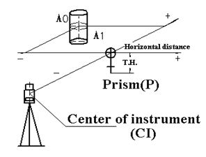
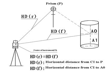
5.5.2 Angle Offset Measurement Mode
Sometimes we need to measure a coordinate of a point such as A1 whose position cannot place a prism, for example the center of a tree, this mode is helpful. It only needs to set the prism on the point which has the same horizontal distance to the instrument as that of the prism to the instrument. Then define the instrument height/target height to start offset measurement, you can get the coordinates of the center of the object.
Note: if you need the coordinate of A0 you should set the height of prism to zero. If you need the coordinate of A1 you should set the height of prism to the real height.
|
Operation Steps |
Key |
Display |
||||||||||||||||||||||||||||
|
[F4] |
|
||||||||||||||||||||||||||||
|
2) Press [F1] (Offset) to see the offset menu. |
[F1] |
|
||||||||||||||||||||||||||||
|
3) Press [1] (Angle Offset) to enter to Angle offset measurement mode. |
[1] |
|
||||||||||||||||||||||||||||
|
4) Collimate the prism P1 and press [F1] (MEAS) to start measurement. It will measure the distance between the instrument and the prism |
Collimate P1 [F1] |
|
||||||||||||||||||||||||||||
|
5) Collimate A0 by horizontal clamp and tangent screws. It displays the SD, HD, and VD from the instrument to A0. |
Collimate A0 |
|
||||||||||||||||||||||||||||
|
6) To display the coordinates of A0 or A1, press (CORD) |
(COORD) |
|
||||||||||||||||||||||||||||
|
Press [F1] (NEXT) to return to Procedure 4. Press [ESC] to return to distance measurement mode. |
||||||||||||||||||||||||||||||
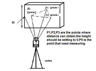
5.5.3 Plane Offset Measurement Mode
Sometimes we wish to obtain the coordinate of some points where we cannot measure directly. Fortunately, we can measure the distances of another points, and all these points are in a plane. In this time the plane offset measurement can be used. The figure is shown as follow.
|
Operation Steps |
Key |
Display |
||||||||||||||||||||||||||||
|
[F4] |
|
||||||||||||||||||||||||||||
|
2) Press [F1] (Offset) to see the offset menu. |
[F1] |
|
||||||||||||||||||||||||||||
|
3) Press [3] (Plane Offset) to enter to Plane Offset measurement mode. |
[3] |
|
||||||||||||||||||||||||||||
|
4) Collimate the prism P1 and press [F1] (MEAS) to start measurement. |
Collimate P1 [F1] |
|
||||||||||||||||||||||||||||
|
5) Press ENT to keep forward to the measurement of the second point. |
ENT |
|
||||||||||||||||||||||||||||
|
6) Collimate the prism P2 and press [F1] (MEAS) to start measurement. |
[F1] |
|
||||||||||||||||||||||||||||
|
7) Press ENT to keep forward to the measurement of the third point |
ENT |
|
||||||||||||||||||||||||||||
|
8) Collimate the prism P3 and press [F1] (MEAS) to start measurement. |
Collimate prism [F1] |
|
||||||||||||||||||||||||||||
|
|
||||||||||||||||||||||||||||||
|
10) Collimate the edge of the plane |
Collimate P0 |
|
||||||||||||||||||||||||||||
5.5.4 Column Offset Measurement Mode
Sometimes we wish to obtain the coordinate of column center where we cannot find. Fortunately, we can measure the distances of another points on the column, in this time the column offset measurement can be used. The figure is shown as follow:
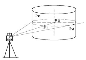
First, measure the distance to the point (P1) of the column surface directly. Then by measuring the azimuth angles of P2 and P3 on the column, you can calculate the distance, azimuth and coordinates of the column center.
Azimuth of the column center is the average value of point of column surface (P2) and azimuth (P3).
|
Operation Steps |
Key |
Display |
||||||||||||||||||||||||||||
|
[F4] |
|
||||||||||||||||||||||||||||
|
2) Press [F1] (Offset) to see the offset menu. |
[F1] |
|
||||||||||||||||||||||||||||
|
3) Press [4] (Column Offset) to enter to Column Offset measurement mode. |
[4] |
|
||||||||||||||||||||||||||||
|
4) Collimate the center of the column (P1) and press [F](Meas) to start EDM then you can obtain the data of a point on the column which is shown as the picture on the right |
Collimate P1 [F1] |
|
||||||||||||||||||||||||||||
|
5) Press ENT to confirm. After measurement, the system will remind you to implement angle measurement of the left point. |
ENT |
|
||||||||||||||||||||||||||||
|
6) Collimate the left point of the column surface (P2) and [F4] (Enter) to finish measurement Then it will display the message to measure the angle of the right point (P3). |
Collimate the left point (F4) |
|
||||||||||||||||||||||||||||
|
7) Collimate the right of the column surface (P3) and press [F4] (SET). Then the distance between the instrument and the column center (P0) will be calculated. |
[F4] |
|
||||||||||||||||||||||||||||
|
Press [F1] (NEXT) to return to Procedure 4. Press [ESC] to return to distance measurement mode |
||||||||||||||||||||||||||||||